 EN
EN

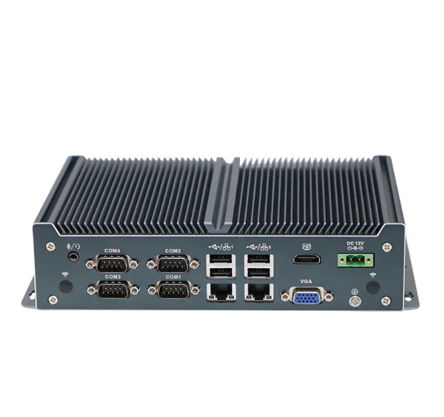
Overheating and Thermal Throttling in Fanless Embedded Computers
Why Passive Cooling Struggles in High-Density or Sealed Environments
A fanless embedded computer relies entirely on its enclosure to dissipate heat through conduction, convection, and radiation—without forced airflow. This passive approach works reliably in well-ventilated spaces with stable ambient conditions. However, it faces critical limitations in confined, sealed, or high-density deployments. When installed inside an enclosed cabinet—or stacked alongside other heat-generating units—ambient air stagnates, trapping thermal energy around the chassis. The enclosure can no longer effectively radiate heat, causing internal temperatures to rise steadily. In such environments, even modest workloads may push components toward their thermal thresholds, undermining the core advantage of fanless reliability.
How Thermal Throttling Impacts Real-Time Performance and Uptime
To prevent hardware damage, modern processors automatically engage thermal throttling when junction temperatures exceed safe operating limits—typically between 95°C and 105°C, per Intel® and AMD® specifications. During throttling, the CPU reduces clock frequency and voltage, directly degrading computational throughput. For time-sensitive applications like PLC-based automation, motion control, or real-time video analytics, these performance dips can cause missed I/O cycles, delayed sensor responses, or inconsistent inference latency. Frequent or prolonged throttling also triggers system-level instability—such as unexplained reboots or watchdog timeouts—jeopardizing operational continuity. Over time, repeated thermal cycling accelerates electromigration and solder joint fatigue, shortening mean time between failures (MTBF) beyond what datasheet ratings predict.
Dust, Vibration, and Environmental Stress on Fanless Embedded Computer Reliability
Dust Ingress Compromising Heatsink Efficiency and Long-Term Thermal Stability
Although fanless designs eliminate intake fans—and thus avoid internal dust accumulation—they remain vulnerable to external contamination. Dust settles on exposed heatsink fins, especially in industrial settings like grain handling facilities, woodworking plants, or cement processing lines. Even a 0.5-mm layer of particulate matter can reduce fin efficiency by up to 30%, according to ASHRAE’s Thermal Management of Electronic Equipment guidelines. This insulating effect raises component temperatures prematurely, triggering earlier and more frequent thermal throttling. Without scheduled maintenance—such as compressed-air cleaning every 6–12 months—thermal derating compounds over time, eroding both performance headroom and long-term reliability.
Vibration and Extreme Temperatures Accelerating Component Fatigue
Fanless systems excel in high-vibration environments by removing rotating parts—but mechanical stress still affects structural integrity. Continuous vibration from motors, conveyors, or vehicle-mounted deployments strains solder joints, PCB traces, and chip-package interfaces. When combined with wide thermal swings (e.g., −40°C to +85°C operating ranges common in outdoor or unheated industrial zones), differential expansion coefficients between silicon, copper, and FR-4 substrates generate cyclic strain. Over months or years, this leads to micro-cracks, intermittent opens, or latent memory errors. Field data from IPC-TR-7532 studies show that vibration-plus-thermal-cycling failure modes account for over 40% of premature field failures in ruggedized embedded systems—often appearing as sporadic resets or corrupted firmware updates before catastrophic failure occurs.
Design Limitations: Materials, Chassis Conduction, and Heat Pipe Effectiveness
In a fanless embedded computer, thermal performance is inseparable from mechanical design. Material choice, interface quality, and structural integration determine how efficiently heat moves from die to ambient. Copper heatsinks offer superior thermal conductivity (~401 W/m·K) compared to aluminum (~237 W/m·K), enabling faster heat spreading in compact form factors—but at higher weight and cost. Aluminum remains the pragmatic standard for most industrial deployments. Equally critical are thermal interface materials (TIMs): high-performance silicone pads or phase-change TIMs must bridge microscopic air gaps between ICs and heatsinks. Poorly applied or degraded TIM can increase junction-to-case resistance by 2–3×, severely limiting heat transfer regardless of heatsink material.
How Chassis Design and Mounting Surface Conductivity Dictate Passive Cooling Success
The enclosure itself functions as a distributed heatsink—especially when constructed from thermally conductive metals like aluminum 6061-T6 or stainless steel 304. Effective conduction requires low-resistance thermal pathways: flat, clean mounting surfaces; uniform clamping pressure via screws or elastomeric pads; and direct metal-to-metal contact. Mounting the unit to a large thermal mass—such as a grounded machine frame or cold plate—can extend the effective heatsink area by 3–5×, significantly lowering steady-state temperatures. Conversely, plastic enclosures or isolation mounts act as thermal barriers, concentrating heat near critical components. Designers must model the full thermal path—from silicon die through package, TIM, heatsink, chassis, mounting interface, and ambient—to identify bottlenecks before deployment.
Proven Mitigation Strategies for Fanless Embedded Computer Deployment
Deploying a fanless embedded computer successfully demands a systems-level approach—not just selecting the right hardware, but engineering its thermal context. Two interdependent levers drive reliability: installation discipline and advanced thermal architecture. Addressing both ensures consistent performance across demanding environments.
Optimizing Installation: Mounting Surfaces, Ambient Airflow, and Enclosure Ventilation
Mount the unit directly onto a thermally conductive surface—ideally bare metal with a thermal conductivity ≥100 W/m·K—and ensure full contact across the designated mounting area. Avoid paint, coatings, or gaskets unless specifically rated for thermal conduction. Provide unrestricted ambient airflow: maintain ≥50 mm clearance on all sides, orient fins vertically to support natural convection, and shield the unit from direct solar exposure or nearby heat sources. In dusty locations, use IP-rated enclosures with strategically placed ventilation slots—positioned to leverage chimney-effect airflow—and schedule periodic inspection and cleaning to preserve fin efficiency.
Advanced Passive Cooling Techniques — Heat Pipes, Vapor Chambers, and Conduction-Optimized Enclosures
When environmental constraints exceed conventional passive limits, augment thermal management with engineered solutions. Heat pipes and vapor chambers distribute localized hotspots across broader surface areas, improving fin utilization and reducing peak die temperatures by up to 20°C under sustained load. Pair them with high-reliability TIMs (e.g., graphite-enhanced pads or sintered metal pastes) and enclosures featuring integrated conduction paths—such as machined aluminum housings with internal thermal rails or copper-inlay chassis. Some next-generation designs integrate graphite films or paraffin-based phase-change materials to absorb transient thermal spikes during burst workloads. These approaches extend passive cooling into applications once reserved for fan-assisted systems—without compromising ingress protection or MTBF.