 EN

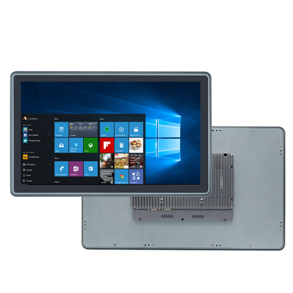
Rolling out touch panel PCs across a plant floor is less about buying hardware and more about matching a computing platform to the physical and operational realities of a specific environment. Get that match right, and the system disappears into the background. Get it wrong, and every shift starts with an operator fighting the interface.
A lot of deployment guides start with the processor. That's backwards. The better starting point is a clear definition of where the unit will live, what it needs to connect to, and who will use it. Everything else, screen size, touch technology, enclosure rating, follows from those answers.
Defining the Operating Environment Before Anything Else
The single most useful planning exercise is to walk the intended installation site and list every environmental stressor the panel PC will face. Not the general category, like "factory," but the specific conditions.
-
Water and chemical exposure. Is there a washdown procedure? How often? What cleaning agents are used? A dry indoor assembly area and a meat processing line with high-pressure washdowns need completely different enclosure ratings.
-
Particulate and airborne contaminants. Wood dust, metal chips, grain dust, and oil mist all behave differently. The first two tend to settle and accumulate. Oil mist coats surfaces and can penetrate seals over time.
-
Temperature range and thermal load. Ambient temperature at the mounting location matters, but so does what's nearby. A panel PC mounted next to a heat-generating drive or furnace sees a much higher local temperature than the room average.
-
Vibration and shock. Machine-mounted units experience continuous low-frequency vibration. Vehicle-mounted units see shock events from potholes and loading impacts. These are different stressors with different design implications.
-
Electrical noise. Are there servo drives, welding equipment, or large inductive loads nearby? These inject high-frequency noise onto power and signal lines, and they can interfere with touch panel operation.
Recording these conditions in writing before any hardware evaluation begins prevents the common mistake of selecting a unit on price and discovering a gap after installation.
Choosing the Right Architecture and Form Factor
Panel PCs come in configurations that suit different workflows. The decision between an integrated panel PC and a separate box PC with a display is one of the earliest forks in the road.
An integrated panel PC combines the computer, display, and touch interface in a single enclosure. It mounts directly into a panel cutout or on a machine frame. This arrangement reduces cable runs, simplifies mounting, and keeps the computing hardware close to the operator. It works well when the operator needs local visualization and the environment near the machine is suitable for electronics.
A box PC paired with a separate display offers more flexibility. The computing unit can be placed in a cleaner or cooler location, like inside a control cabinet, while the display sits at the operator station. This architecture makes sense when the machine-side environment is too harsh for electronics, when multiple displays need to connect to one computer, or when the compute platform and the display have different replacement lifecycles.
A few form factor considerations that tend to get overlooked:
-
Panel cutout dimensions. The cutout is determined by the panel PC's rear housing, not the front bezel. Confirm the actual cutout drawing before cutting anything. A few millimeters of error in the cutout means the unit either won't seat properly or leaves an unsightly gap.
-
Mounting depth. The rear of the panel PC needs clearance for connectors, cable bends, and in some cases, expansion cards. In shallow cabinets, a low-profile unit is the difference between fitting and not fitting.
-
VESA and arm mounting. Machine-mounted and articulating arm installations rely on VESA patterns. Verify the VESA hole pattern and screw depth limits, because over-length screws can damage internal components.
-
Weight and center of gravity. A panel PC mounted on an arm or a vehicle puts stress on the mounting hardware. A heavier unit may require a beefier bracket or a different mounting strategy.
Matching Touch Technology to the Actual Operator
Touch technology is where a lot of deployments go sideways, not because the technology is bad, but because the wrong technology was chosen for the hands using it.
Projected capacitive touch panels dominate modern panel PCs. They support multi-touch gestures, have excellent optical clarity, and respond to a light touch. In clean, indoor environments with bare-handed operators, they are the best choice.
The catch is glove compatibility. Standard projected capacitive panels do not respond reliably to thick work gloves. Some manufacturers offer glove-tuned firmware that improves performance with thin nitrile or latex gloves, but thick leather or cut-resistant gloves remain problematic. In those cases, resistive touch technology is the more practical option. Resistive panels respond to pressure rather than capacitance, so they work with any glove type and even with a stylus. The trade-off is lower optical clarity and no multi-touch support, but for many industrial HMI applications, single-touch operation is entirely sufficient.
The table below summarizes how the two technologies compare for common industrial scenarios.
| Factor | Projected Capacitive | Resistive |
|---|---|---|
| Bare finger operation | Excellent | Good |
| Gloved hand operation | Limited (firmware-dependent) | Excellent |
| Multi-touch support | Yes | No |
| Optical clarity | High | Moderate |
| Response to wet screen | Poor to moderate | Moderate |
| Durability against impact | Good | Moderate |
| Cost | Higher | Lower |
A common mistake is specifying capacitive touch for a food processing or cold storage application where operators wear insulated gloves. The panel works fine in the lab and fails on the floor. Walking the site and observing what operators actually wear on their hands is a five-minute exercise that prevents months of frustration.
Planning Connectivity, Power, and I/O
The interface count on a panel PC determines what it can connect to without external adapters. Every adapter added to a deployment is another potential failure point and another component to source and stock.
Start by listing every device the panel PC needs to communicate with. A typical machine-side installation might include:
-
A PLC or motion controller over RS232, RS485, or Ethernet
-
A barcode scanner or RFID reader over USB
-
A label printer or report printer over USB or Ethernet
-
A plant network connection over a second Ethernet port
-
Digital sensors or actuators over GPIO
That list quickly consumes ports. A panel PC with a single Ethernet port and two USB ports will need adapters for most real installations. Specifying a unit with dual Ethernet, four or more USB ports, and multiple serial ports reduces the adapter count and simplifies cable management.
Power is the other connectivity consideration that gets underestimated. Industrial environments rarely provide a clean 24V DC supply. Wide voltage input ranges, typically 9 to 36V DC or wider, allow the panel PC to ride through the voltage sags and surges that occur when nearby equipment switches on and off. Reverse polarity protection and surge handling are baseline expectations. A unit that lacks these features may work fine in a lab and fail intermittently in the field, where the failure is difficult to diagnose and easy to misattribute to software.
Power over Ethernet is worth considering for panel PCs mounted in locations where running a separate power cable is difficult or expensive. A PoE-enabled panel PC receives both power and data over a single Ethernet cable, which simplifies installation and reduces cable clutter. The trade-off is that PoE power budgets are limited, so this approach suits lower-power panel PCs and may not be viable for units driving large displays or running heavy compute loads.
Software Deployment and Configuration at Scale
The hardware installation is usually the straightforward part. Software configuration is where multi-unit deployments become complex.
When a panel PC runs a standard operating system like Windows or Linux, the configuration work includes installing the HMI or SCADA runtime, setting up communication drivers, configuring user accounts, and applying security policies. For a single unit, this is manageable. For fifty units across a plant, doing it manually introduces inconsistency and consumes engineering time.
A more efficient approach is to complete software imaging at the production or staging stage. A controlled system image, including the operating system, drivers, runtime software, and configuration files, can be installed and tested before the unit ships. At the deployment site, the unit powers on, connects to the network, and is ready for final configuration. This method reduces on-site engineering hours and ensures that every unit in a deployment starts from the same baseline.
Communication driver configuration is a common source of deployment friction. The panel PC needs to speak the protocol that the PLC or controller uses. Modbus TCP and OPC UA are widely supported and well documented. Proprietary protocols may require vendor-specific drivers that need to be sourced and licensed. Confirming driver availability before hardware selection avoids a situation where the panel PC arrives and cannot communicate with the equipment it was purchased to control.
A Deployment Where Power Quality Was the Hidden Problem
An integrator was commissioning a set of panel PCs on a packaging line. The units were mounted at each station, connected to the line's PLC over Ethernet, and running a custom HMI application. Everything worked during the day shift.
The night shift reported intermittent touch failures and occasional screen freezes. The problem never occurred during testing. It only appeared when the line was running at full speed with all stations active.
The investigation took several days. The panel PCs were within their temperature and vibration specifications. The Ethernet cabling tested clean. The HMI software logs showed no errors. Eventually, a technician monitoring the power input with an oscilloscope noticed voltage transients on the 24V DC supply whenever a particular servo drive engaged. The transients were fast and short, but they were enough to disrupt the panel PC's touch controller.
The fix involved installing a line filter on the power feed to the affected panel PCs and adding a small isolation transformer on the touch controller's signal path. The root cause was not a defective panel PC. It was a power quality issue that only manifested under specific operating conditions, and it took a methodical approach to isolate.
This scenario illustrates why power conditioning and filtering deserve attention during the planning phase. Specifying a panel PC with robust input filtering and, where necessary, adding external line conditioning is a small cost compared to the downtime and diagnostic effort that power-related failures generate.
Maintenance, Longevity, and Lifecycle Planning
Panel PCs in industrial settings are expected to run for years, often in continuous operation. Planning for maintenance and eventual replacement is part of a responsible deployment.
A few practices that extend service life and simplify maintenance:
-
Regular screen cleaning. Dust and oil buildup on the touch surface degrades touch sensitivity and can cause false touches. A defined cleaning schedule with appropriate cleaning agents prevents this.
-
Connector inspection. Vibration can loosen connectors over time. Periodic checks and re-seating of power, network, and serial connections catch problems before they cause a failure.
-
Thermal path maintenance. For fanless units, dust accumulation on the external heatsink or chassis surfaces reduces heat dissipation. Cleaning those surfaces restores thermal performance.
-
Spare unit strategy. Keeping a configured spare panel PC on site means a failed unit can be swapped out in minutes rather than waiting for a replacement to ship. The spare should be imaged and configured identically to the deployed units.
Lifecycle planning is equally important. Industrial panel PCs are often expected to remain in service for five years or more. Processors and chipsets have shorter production lifecycles than that. A manufacturer that commits to long-term availability of a specific platform, and communicates end-of-life timelines well in advance, makes it possible for plant operators to plan replacements without disrupting production.
Shenzhen Xin Saike Technology, operating as XSK, has been building industrial computing hardware since 2007 from a manufacturing base in Dongguan covering over 5,000 square meters. The product range spans mini industrial PCs, embedded systems, industrial panel PCs, and network security platforms, with certifications including CCC, CE, FCC, RoHS, and TUV. For deployment teams that need panel PCs configured for specific I/O requirements, environmental ratings, or mounting arrangements without committing to large volumes, the OEM and ODM services and low minimum order quantities provide a practical path from specification to installed hardware. A panel PC deployment succeeds when the hardware matches the environment, the software is configured before the unit ships, and the manufacturer understands what it takes to keep a system running after the installation crew leaves.
Table of Contents
- Defining the Operating Environment Before Anything Else
- Choosing the Right Architecture and Form Factor
- Matching Touch Technology to the Actual Operator
- Planning Connectivity, Power, and I/O
- Software Deployment and Configuration at Scale
- A Deployment Where Power Quality Was the Hidden Problem
- Maintenance, Longevity, and Lifecycle Planning